Dust & water resistant IP54 (splash proof, not immersible)
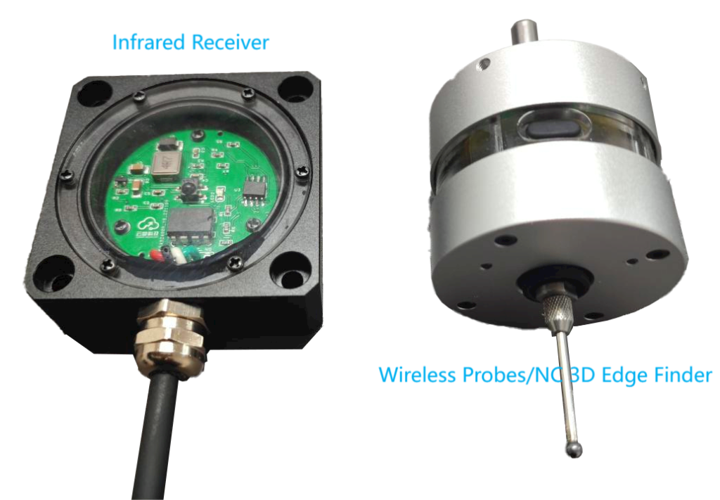
Weight
160g
Receiver Parameters
Voltage
5~24V DC
Current
50 mA
Signal mode
NPN PNP NC NO
Fixed mode
M4 screw fixingMagnetic backing
Signal Wire length
3m
Receiving distance
2m
Weight
180g
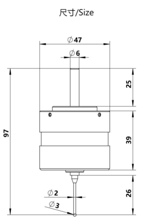
2. Structure
No.
Name
Materials
1
6MM clamping handle
Stainless
2
Seal Ring A
Rubber
3
M3 AdjustmentJackscrew ×4
Carbon steel
4
Back Cover
Aluminum
5
Seal Ring B
Rubber
6
Li-ion Battery 900 mAh
/
7
Acrylic Middle Frame
Acrylic
8
Seal Ring C
Rubber
9
Main Control Board
PCB
10
Gold Plated Contact Plate
PCB
11
Front Cover
Aluminum
12
Tripod
Stainless
13
Silicone Dust Cover
Silicone
14
M2.5 Stylus
Tungsten Steel/Ruby
3. Video
4. Operation
Warning
Probe use is prohibited with the spindle rotation on
NPN
PNP
NPN-NO Normal Open
PNP-NO Normal Open
NPN-NC Normal Close
PNP-NC Normal Close
Generally, if the system supports it, it is recommended to use NC normally closed, with a shorter relative delay in wiring. a. When the system is NPN, COM connects to the system signal GND, and the system probe input signal connects to NC or NO according to normally open or normally closed. b. When the system is PNP, COM connects to the system signal VCC, and the system probe input signal connects to NC or NO according to normally open or normally closed.
Charging with Type-c port, does not support fast charging, input 5V1A,about one hour full.Red indicator light when charging, green indicator light when full. Tip :Prohibit the use of Apple type-c cable, different definitions will lead to damage.
When triggered by normal measurement, the indicator light shows green;When triggered by low battery (battery voltage ≤ 2.9V), the indicator light shows red to remind charging. Tip:When the indicator light shows red for the first time, it can be used for 3~4 days, you need to charge it as soon as possible.
The receiver is a 5-core signal output line, respectively, power supply 5~24V+ (red);GND (black); COM (white); NC (green) NO (yellow). Support NPN and PNP normally open or normally closed mode.Among them, V+ can be connected to the power supply interface within the range of 5~24V on the system, and the operation current is only 50mA.COM is set according to the probe signal input mode supported by the system.
Receiver installation requirements. Receiver is generally installed on the side or topof the machine without blocking parts, you can use the back of the magnetic temporarily fixed, hand-held probe press trigger in the range of travel to test whether the normal reception (the receiver lights up red), to determine the appropriate installation position after punching holes to install M4 fixing screws.
Before shipment, the concentricity of the probe will be adjusted to 0.05 (because oftransportation vibration, even if adjusted to 0.01 to receive the goods can not guarantee the original accuracy), after receiving the goods need to be adjusted to 0.01mm.