
Top 3Desktop Injection Molding Machine
Bring molded prototypes and small-batch production into your workspace. Combine 25-ton servo clamping with hydraulic injection and controlled part ejection.


Control each stage of the molding cycle
Servo-driven mold movement, accumulator-assisted injection and adjustable ejection in one compact platform.
Servo ball-screw clamping
25-ton clamping force with adjustable mold opening travel to suit the mold and part removal process.
Servo-controlled ejection
A 60 mm ejector stroke with adjustable distance and speed helps configure the part release sequence.
Accumulator-assisted injection
Hydraulic injection with an accumulator supplies the injection stage, paired with servo-driven mold movement.
7-inch touchscreen
Set molding parameters and operate the machine from a clear touchscreen interface.
Nozzle retraction
Nozzle retraction (NRM) moves the nozzle away from the mold when required by the process. It is distinct from melt decompression by retracting the injection plunger.
Compact production workflow
Develop molded prototypes and plan small-batch runs with a machine sized for compact manufacturing spaces.
A closer look at the Top 3
Explore the clamping mechanism, hydraulic power unit and electrical control cabinet through real machine details.
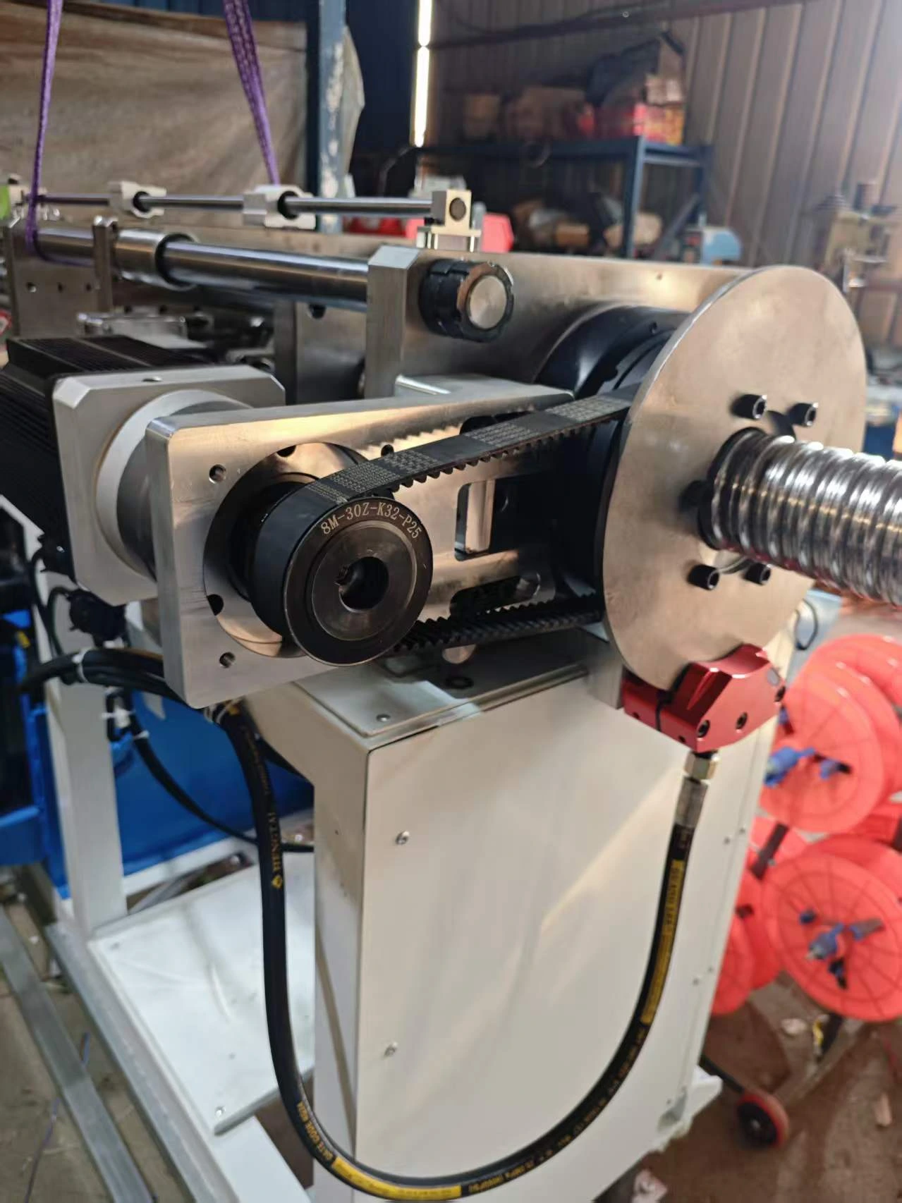
Servo ball-screw clamping
A closer view of the servo motor, timing belt and ball screw that drive the clamping mechanism.
Adjust mold opening travel to suit the tooling and leave the clearance needed for part removal. Servo-driven motion supports setup for different mold thicknesses and molding cycles.
- Servo motor & belt transmission
- Ball-screw drive
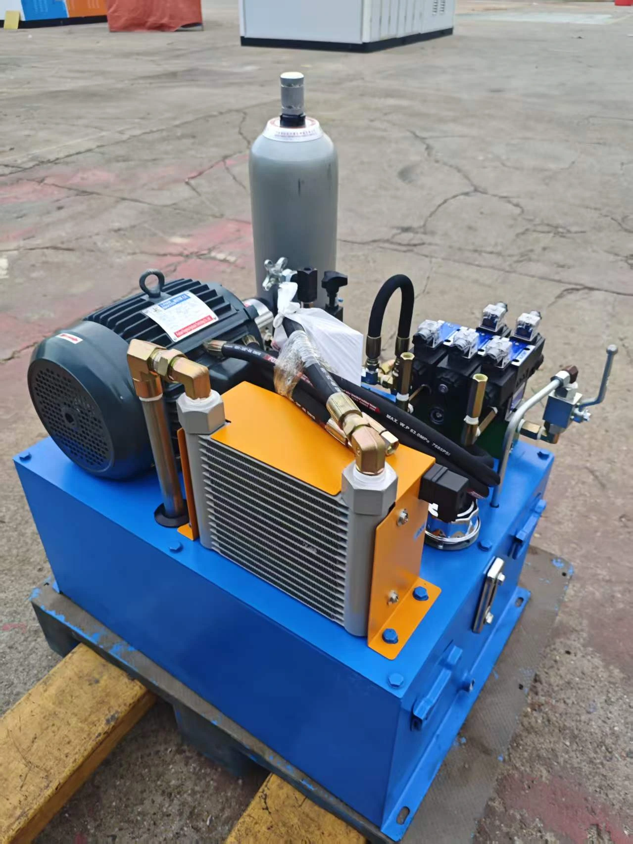
Accumulator-assisted hydraulic injection
The hydraulic power unit brings together the motor, accumulator, valve manifold and oil cooler for the injection system.
The accumulator stores hydraulic energy for the injection stage, while the valve manifold directs oil flow and the cooler helps manage oil temperature during operation.
- Accumulator & valve manifold
- Oil cooling
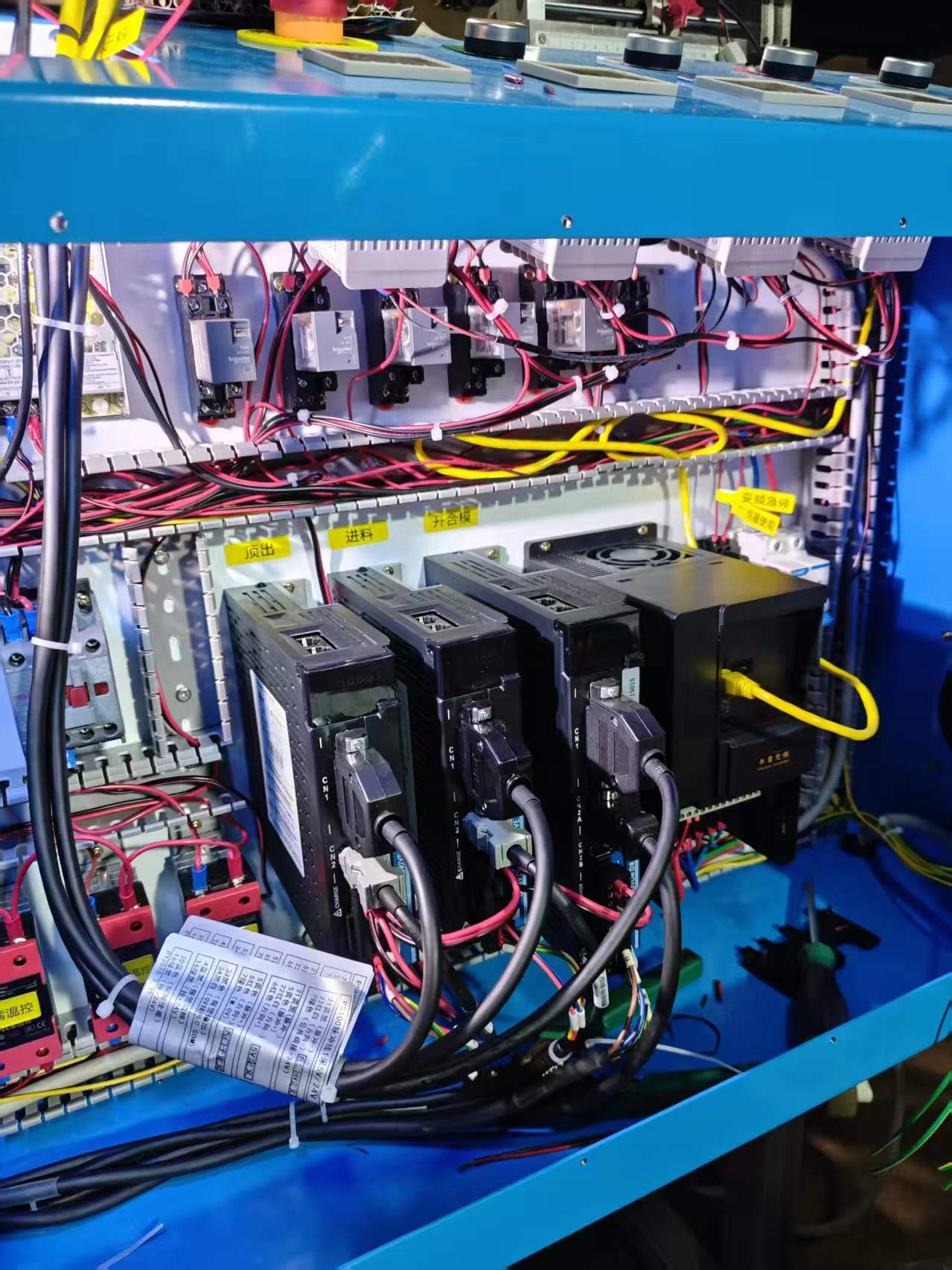
Integrated electrical control
See the servo drives, control components and wiring layout inside the machine cabinet.
The cabinet groups the servo drives, power supplies and temperature-control components for inspection and maintenance. Drive-to-axis assignments are defined by the final electrical drawing.
- Servo drives
- Control wiring
Plan around the space your mold needs
Check mold thickness, mounting dimensions and the clearance needed to remove the part before selecting your tooling.
Check the complete mold assembly
Send the mold drawing for a review of platen fit, mounting holes, nozzle alignment, ejector interface and part removal space.
Set the opening to match the process
Adjust mold movement to provide the required access for part removal. Allow room for inserts, undercuts, sprues and any handling equipment.
Mold closing stroke is the travel of the moving platen. Maximum platen daylight is the distance between the mold mounting faces when fully open. Confirm the available clearance with the complete mold assembly and final machine drawing.
Top 3 at a glance
Core motion, injection and control specifications for planning your molding setup.
Machine & hydraulic system
| Machine dimensions | L192 × W98 × H128 cm | Power supply | 220 V, single phase |
|---|---|---|---|
| Motor power | 5 kW | Heating power | 3 kW |
| Hydraulic system pressure | 12 MPa | Oil tank capacity | 60 L |
Injection unit
| Plasticizing screw diameter | 20 mm | Screw stroke | 150 mm |
|---|---|---|---|
| Screw speed | 150 rpm | Injection plunger diameter | 25 mm |
| Injection plunger stroke | 150 mm | Injection volume | 73 cm³ |
| Max. shot weight (PS) | 50 g | Max. injection pressure | 160 MPa |
| Injection flow rate (volumetric) | 50 cm³/s | Injection plunger speed | 100 mm/s |
| Heating zones | 4 | Max. heating temperature | 400 °C |
| Nozzle protrusion relative to platen | 20 mm | Injection drive | Accumulator-assisted hydraulic |
Clamping & mold space
| Clamping force | 25 tons | Clamping drive | Servo ball screw |
|---|---|---|---|
| Mold closing stroke | 400 mm | Max. platen daylight | 450 mm |
| Minimum mold thickness | 120 mm | Maximum mold size | 280 × 380 mm |
| Platen dimensions | 380 × 280 mm |
Ejection & operation
| Ejector drive | Servo | Ejector stroke | 60 mm |
|---|---|---|---|
| Ejector adjustment | Distance and speed | Touchscreen | 7 inches |
| Nozzle retraction (NRM) | Included |
Shot weight is referenced to PS in g; injection volume is given in cm³. Volumetric injection flow rate (cm³/s) and injection plunger speed (mm/s) are different parameters. Confirm machine weight, installation requirements and the mold mounting drawing in your quotation.
From machined components to machine assembly
A look inside the manufacturing process, from platen machining to system assembly.
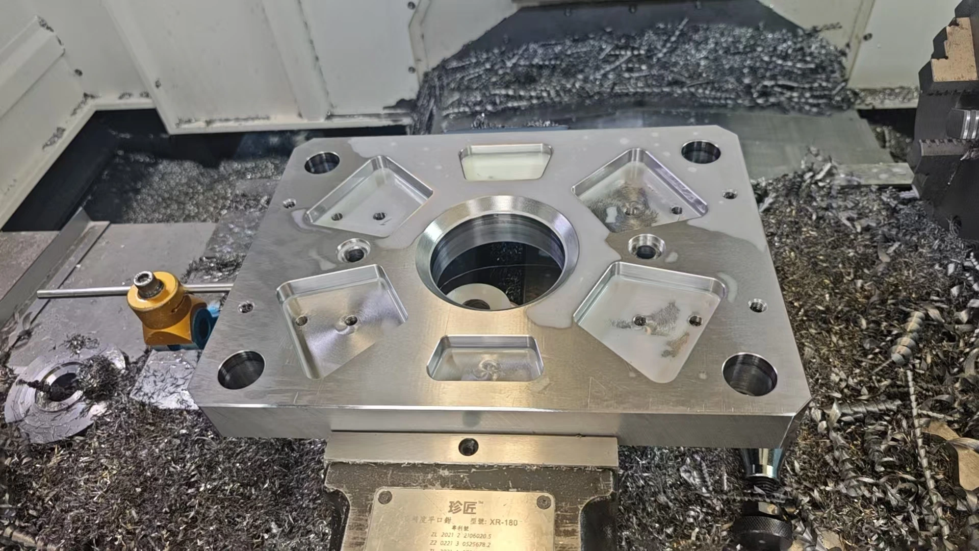
Platen machining
CNC machining of a platen before machine assembly.
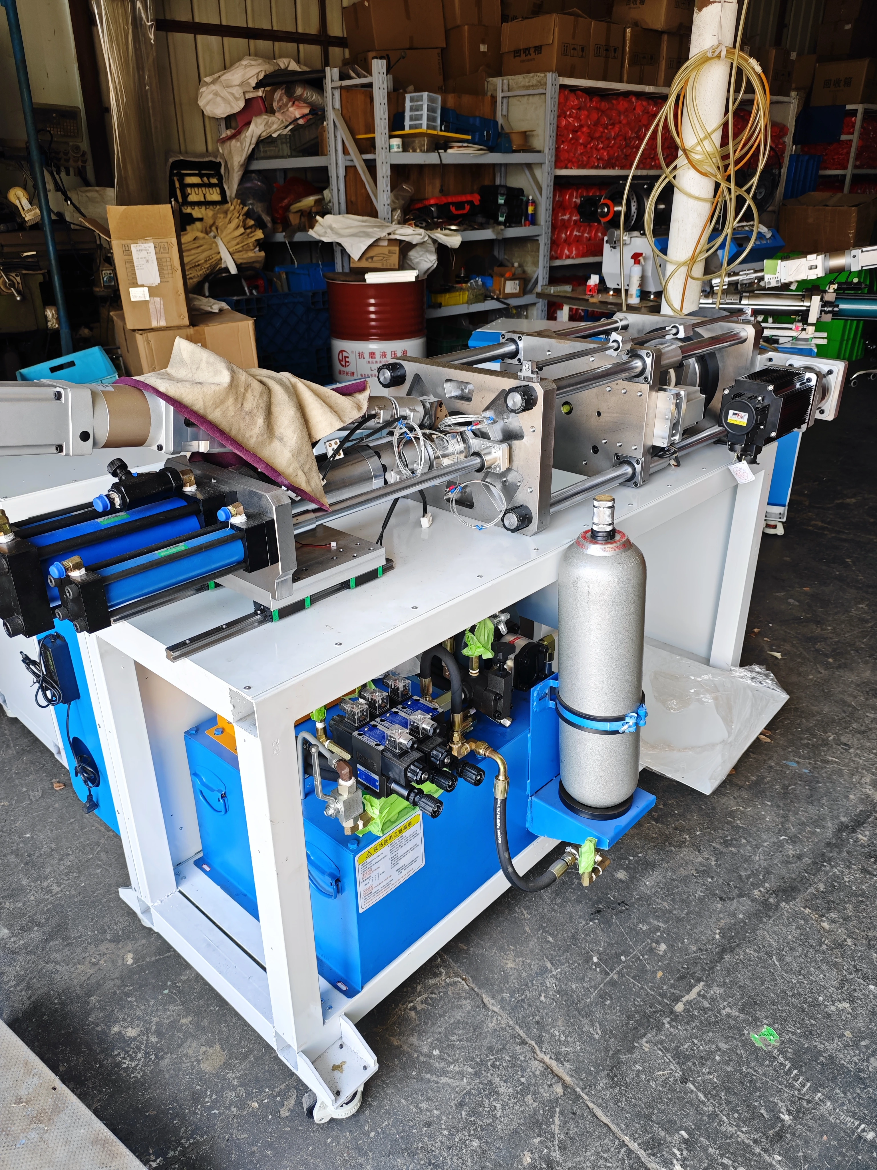
Machine assembly
Assembly-stage view of the frame, injection unit and hydraulic system.
Manufacturing and assembly photos. Guards and exterior panels may not yet be fitted; these are not finished delivery configurations.
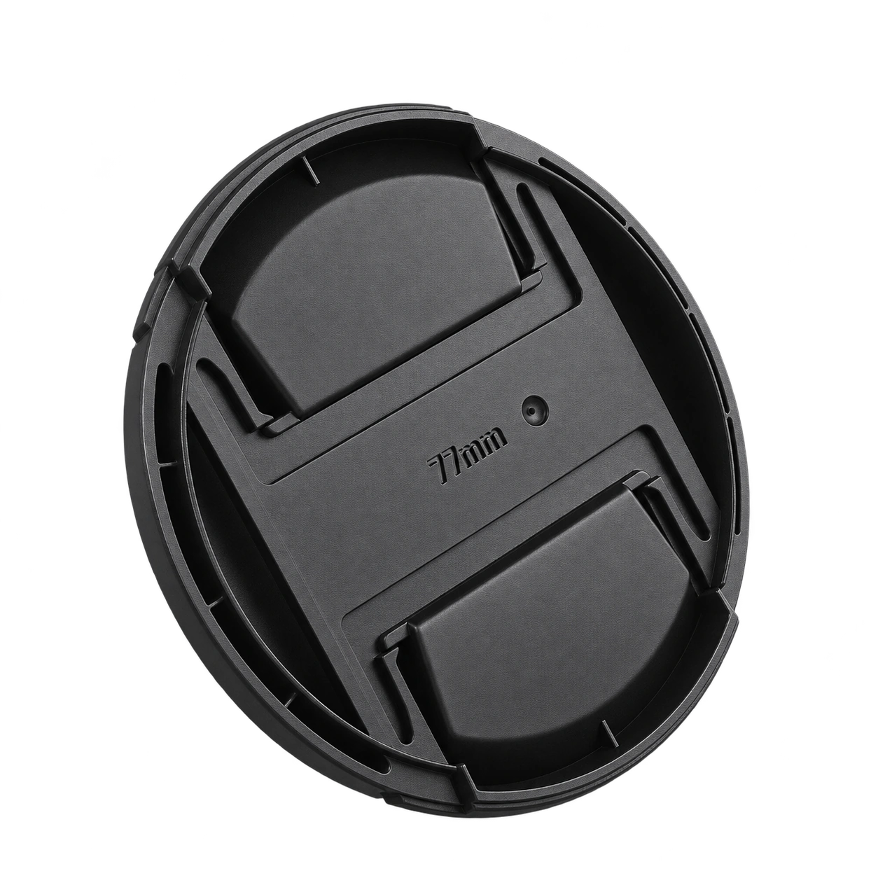
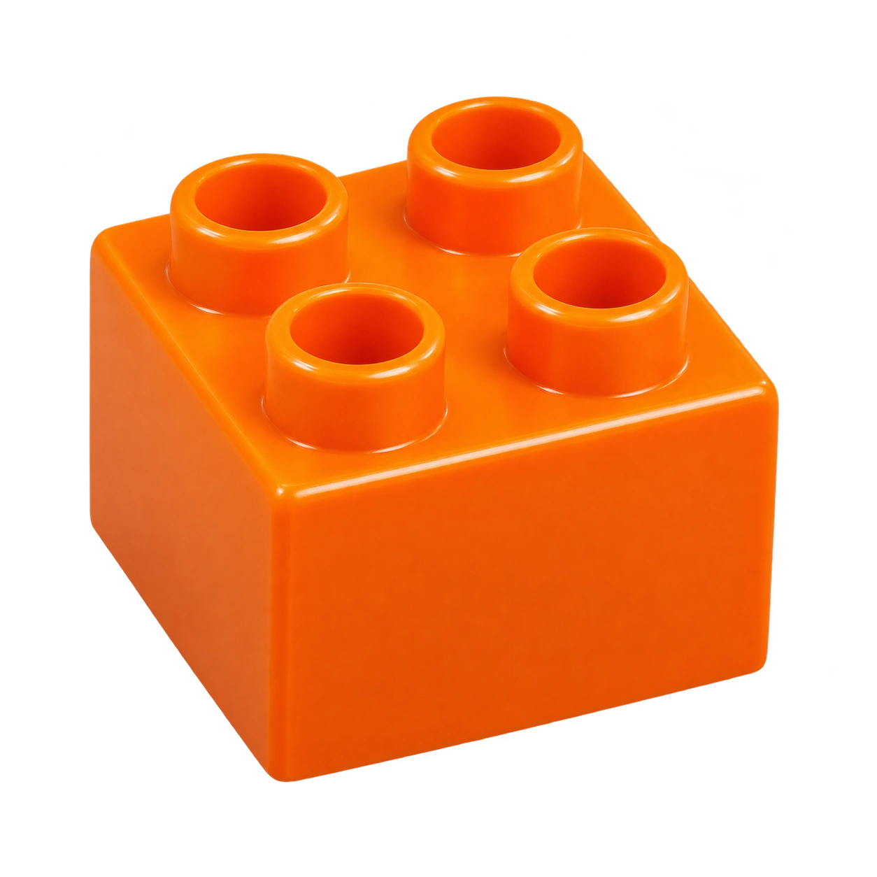
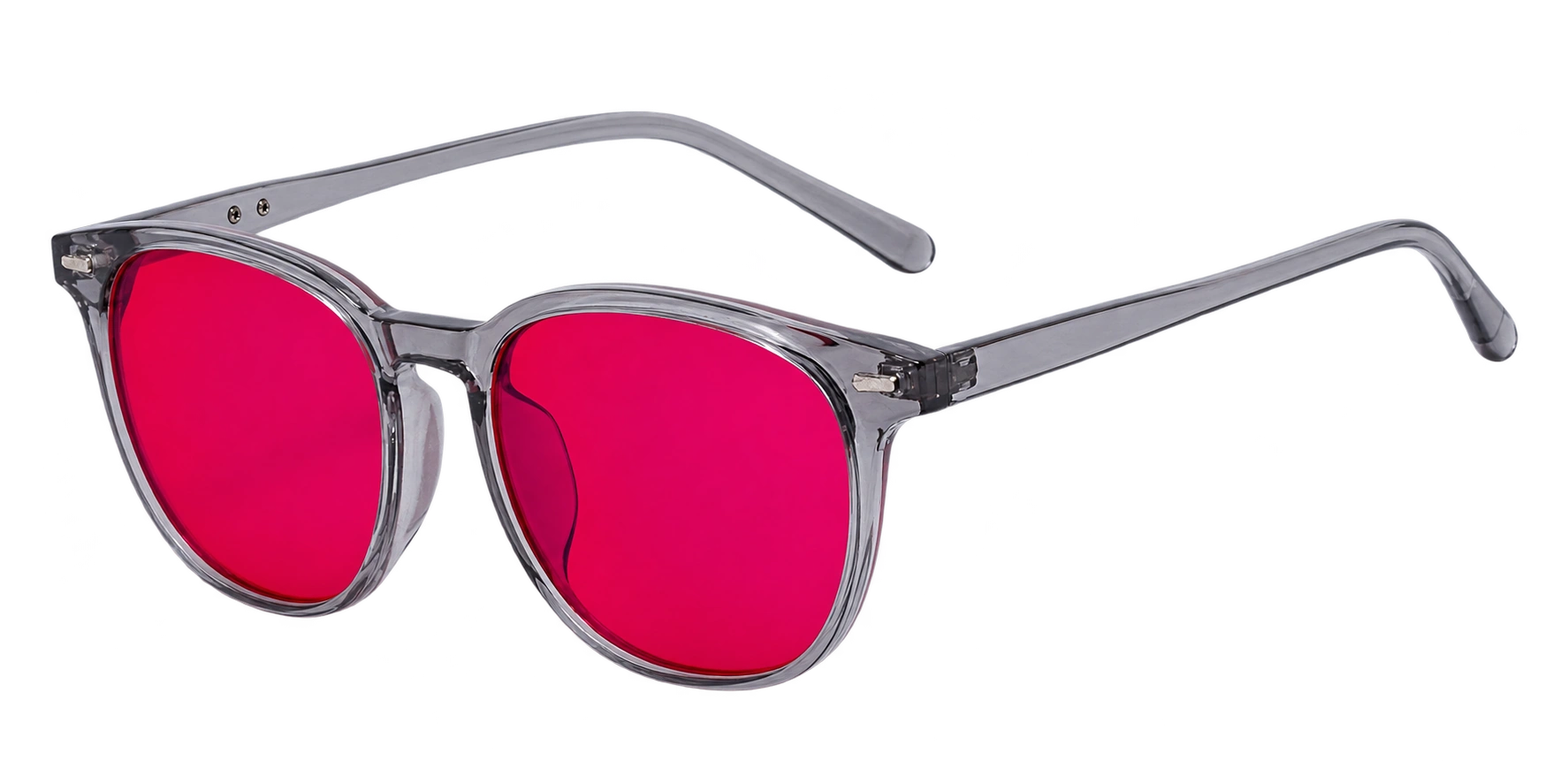
From molded prototypes to small production runs
Evaluate part geometry, tooling and repeatable workflows for small plastic components, functional prototypes and product development.
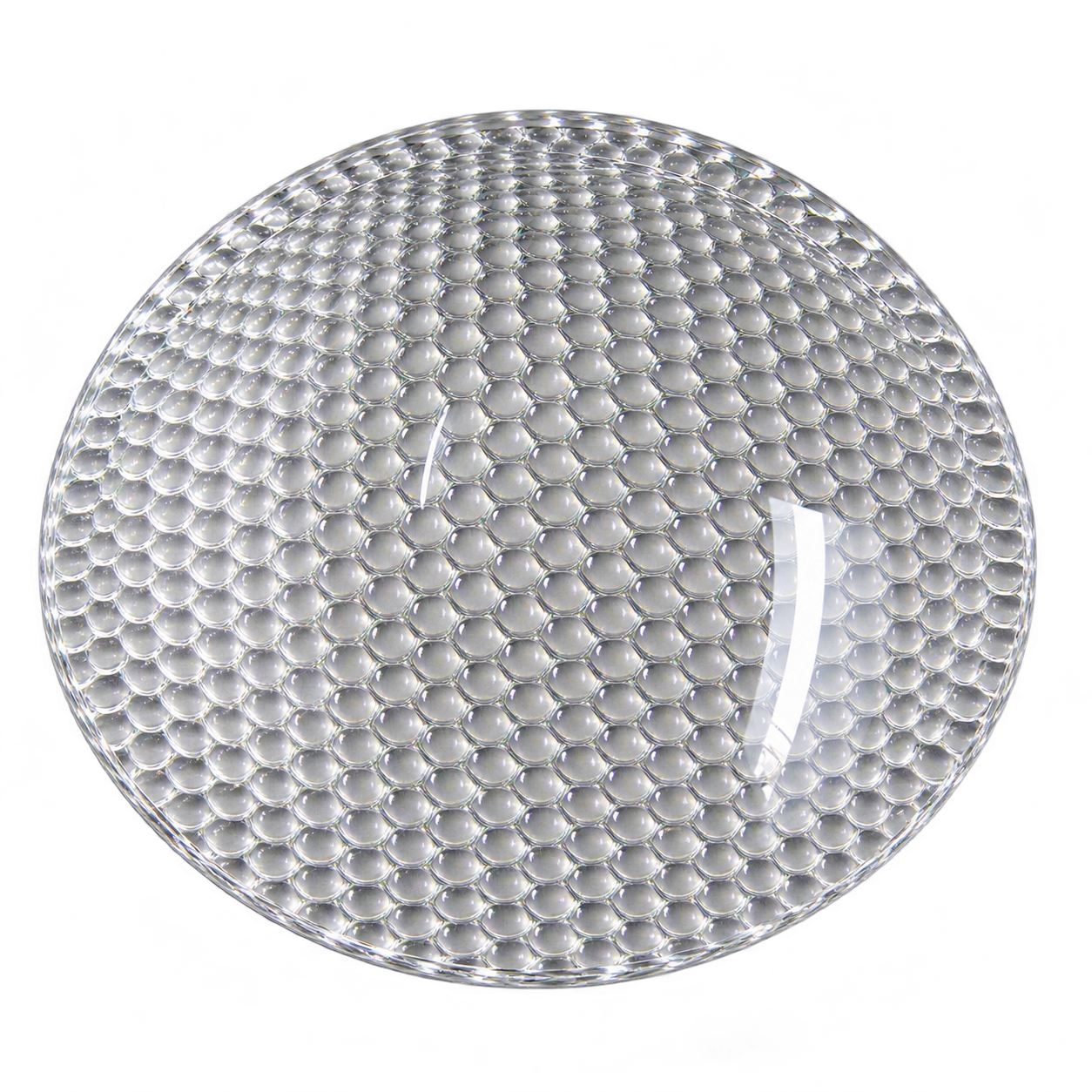
Choose the resin for your part
Material compatibility is grade- and configuration-dependent. Confirm drying and processing requirements with the resin supplier.
Optional auxiliary equipment
Match material preparation and handling equipment to your resin, production volume and installation.
| Equipment | Purpose | Selection notes |
|---|---|---|
| Material dryer | Resin drying | Drying temperature, time and moisture requirements depend on the resin grade. |
| Material loader | Automatic feeding | Confirm pellet compatibility, conveying distance and hopper interface. |
| Storage hopper | Material storage | Select capacity and moisture protection to suit the process. |
| Part removal robot | Automated handling | Confirm mounting, reach, machine interface and guarding. |
| Voltage transformer | Supply adaptation | Size against the confirmed input voltage, phase, current and machine load. |
Accessories are quoted separately. Confirm the final configuration and compatibility before ordering.
Frequently asked questions
Is Top 3 an all-electric injection molding machine?
Top 3 combines servo ball-screw clamping and servo ejection with accumulator-assisted hydraulic injection. It is a hybrid configuration.
What is the difference between mold opening stroke and daylight?
Mold opening stroke is the travel of the moving platen during opening. Maximum platen daylight is the distance between the mold mounting faces when fully open. The listed maximum daylight is 450 mm; mold closing stroke is 400 mm. Actual part removal clearance depends on the complete mold assembly and machine setup.
Does 50 g mean that every molded part can weigh 50 g?
No. The 50 g figure is a maximum shot weight referenced to polystyrene (PS). The usable amount depends on the resin and processing conditions. The shot includes the part and feed system, with an appropriate melt cushion maintained in the process; it is not the net part weight.
Can Top 3 process ABS and PC?
ABS and PC are candidate materials, alongside PP, PE, PS, POM, PA, PMMA and TPE. Suitability depends on the exact resin grade, barrel temperature configuration, drying, mold design and process settings. Send the material datasheet and part drawing for review.
What should I send to get a quotation?
Send your part drawing or 3D model, resin grade, part weight, mold dimensions, target output, destination and available electrical supply. Include runner weight and any insert or demolding requirements.
What warranty support is available?
The warranty period is 12 months. Parts for covered failures and remote replacement guidance are provided under the agreed warranty terms. After the warranty period, replacement parts are available at cost or purchasing guidance can be provided.
Start with your part.
Build the right molding setup.
Share your drawings, resin grade and production goals. We will review mold compatibility and prepare a Top 3 quotation for your application.